


CHOUR - Watch adjuster / chronocomparator RM1
Device: Chronocomparator (mechanical watch adjuster, Timing machine)
Date: December 2018-January 2019. Revision schematic, June 2022.
Type: PC-RM1
Brand: Chour
Last software version: V1.4
Principaux constituants : Arduino pro micro, sensors, display
Version française : 
related information
Timing machine PC-RM4
Sensor for timing machine
Overview
The device presented here is a low cost workshop mechanical watch adjuster. It is also called Chronocomparator. It allows to check the accuracy of a watch (more or less a certain number of seconds per day) and to adjust it to minimize this drift.
I will not detail the operation of a mechanical watch. There are many explanations on the net. Let's just say that the adjustment can be done using one or two devices (it depends on the watches) which act on the spiral spring of the balance and allow:
- to increase or decrease the frequency of the pendulum beat
- To ensure that the duration of a "tick" is equal to the duration of a "tock" (regularity of movement. This setting is not always present).
The picture comes from http://www.montrespourtous.org/
How a watch adjuster works?
To make explanations easier, we will consider that a watch is "ticking" (the little sound you hear that is produced by the escapement of the watch). This notion of "tick" and "tock" is arbitrary, a "tick" can be a "tock" and vice versa. But once you have decided that a noise is a "tick", the next is a "tock".
A watch adjuster detects the "tick" and "tock" of the watch, measures the period between two "ticks" (or "tock") and compares this period with that expected according to the design of the watch.
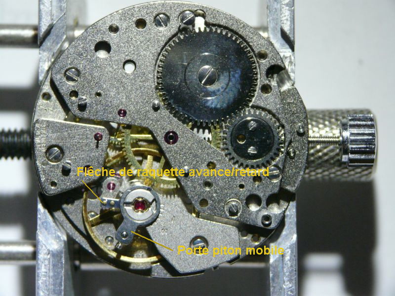
A display shows the difference between the measured value and the expected value. If the measured value is lower than the expected value, the watch will advance, if it is longer, it will delay. The goal is to make this difference tend towards zero by acting on the regular corrector which controls the advance (marked A(vance) or F(ast)) and the delay (marked R(etard) or S(low)).
It also makes it possible to measure the regularity of the movement, in other words, the difference in duration between a "tick" and a "tock". Again, the goal is to make this difference tends to 0 by acting on the stud support (when present, otherwise it is more complicated) that allows the adjustment of the alignment of the pendulum with the pallet fork and the escape wheel.
Notion of beats, period and frequency
The expected duration or frequency values depend on the caliber of the watch. The table below gives some common values:
- The number of beats Bh per hour (number of "tick" or "tock") per hour.
- The frequency of the beat Fs = Bh/3600
- The beat period in milliseconds (ms) with P = 1/Fs (time between two "tick" or between 2 "tock")
- The duration D of a "tick" or "tock" = P/2
| Bh | Fs | P | D |
| 18000 | 2,5Hz | 400ms | 200ms |
| 21600 | 3,0Hz | 333ms | 166ms |
| 28800 | 4,0Hz | 250ms | 125ms |
| 36000 | 5,0Hz | 200ms | 100ms |
Some features of the watch adjuster
This watch adjuster aims to:
- A very low realization cost (about 30 €), as long as you are a minimum handyman.
- A reduced size in order to be easily placed on a bench always too crowded ...
- Very easy to use.
- Good accuracy (we will come back to it).
If you are someone ordered and you have room, then you can use a laptop and in this case, I recommend the Watch-o-scope. Note however that the device that I propose here can also be connected to a microcomputer. So you have two devices for the price of one.
The main features are:
- Power supply via USB.
- Select the number of beats per hour.
- Triggering, stopping the measurement.
- Measure and display the difference between the measured period of the watch and the expected period.
- Measure and display the difference between the duration of a "tick" and the duration of a "tock".
- Measure and display the number of seconds in advance or delay per day.
- Choice between external piezo sensor and integrated microphone sensor (optional).
- Analog signal output to connect the unit to the microphone input of a computer.
- Theoretical resolution of 4μs and theoretical accuracy of 1% (see the chapter dedicated to this subject for more information).
General operation of a watch adjuster
A watch adjuster consists of:
- An electronic sensor: it is used to detect "tick" and "tock". A piezoelectric sensor is usually used or a microphone, or, why not, an optical sensor.
- An amplifier: for a piezoelectric sensor or a microphone, the generated signal will be very weak. It will amplify while seeking to reject the noise.
- Nowadays, a microcontroller to make measurements and to manage the display.
The sensor
The sensor generally used is electric piezo type (piezo thereafter) that uses the properties of certain materials to generate an electrical voltage when they undergo a mechanical stress such as, for example, a shock.
We find such sensors for about 1.5 € 10. For my part, I took a 20mm diameter model.
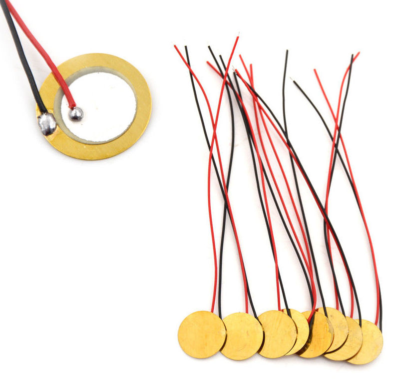
Piezo sensor
You can also recover such a sensor on an old quartz watch with alarm since the body that produces the sound of the alarm is also a piezo sensor.
Why are we using this type of sensor preferentially? It is inexpensive, very sensitive to shocks and not very sensitive to ambient noise.
An electret microphone can also be used. For my part, I tested this model that works satisfactorily. It has its own preamplifier, all sold at around € 1.5.
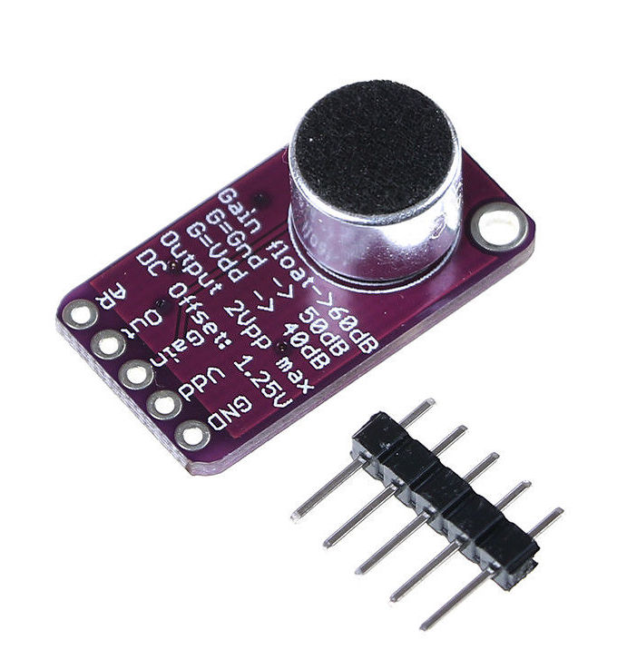
Microphone sensor
If you use this solution, you will not have to build an amplifier since it is integrated. By cons, it is less powerful than the piezo sensor and above all, it is very sensitive to ambient noise (it's normal, it's done for that). A door that closes, a car that passes, etc. and all measurements are disturbed.
The amplifier
If you use the piezo sensor, you will need to build an amplifier to bring the signal value to a level that can be used by the microcontroller.
Here, no hesitation, use the schematic proposed by http://www.watchoscope.com/amplifier.html but with some improvements (see below). It is very suitable and inexpensive.
However, it has the disadvantage of requiring a voltage of 9V while the watch adjuster is powered via the USB socket of its microcontroller and therefore has only 5V.
I replaced the TL074 used by a LM324. It is PIN to compatible PIN. The editing works as well as the TL074 (I did both) but can be powered in 5V.
I also added a signal shaping circuit so that it is easier to use by the microcontroller. To do this, I used the 555 monostable stainless (designed in 1970! Probably the most famous analog circuit and the best known in the world of electronics) that can be found everywhere for a handful of cherry tails.
This monostable generates a rectangular signal from the analog signal.
To trigger the 555, it is necessary to invert the input signal. A transistor (here, a BC109 because I had full but you can also use a BC548 or any bipolar NPN general transistor for small signals) is used for this purpose.
Microcontroller
The microcontroller is an Arduino Pro Micro ATmega32U4 5V 16MHz (around 3,5€). You can download the software on the present page.
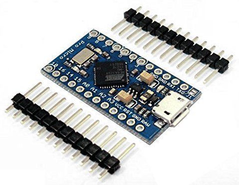
Microcontroller pro-micro
Display
The reference of the LCD display is IIC-I2C-TWI-SP-I-Serial-Interface1602, 2 rows, 16 characters (around 2,5€).
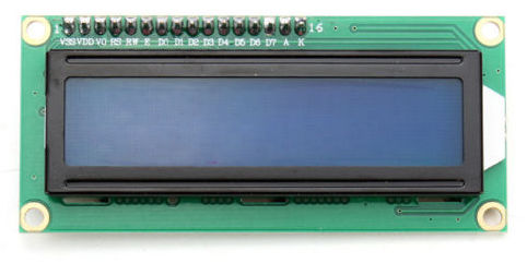
Display
The other components
There are resistors, capacitors, potentiometers, LED, jack, contactor, etc. and a test pad for soldering the components. If you are an electronics technician, you probably have all that in stock. Otherwise, you will need to order them. You should not get by for more than 10 to 15 €.
A word on the contactor anyway: it is a rotary model with momentary pusher that we find for about 2€ 5.
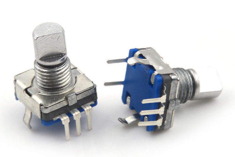
Contacteur
Then you have to put all this in a box and tinker a watch vice to put the sensor. Again, the modified amplifier proposed by http://www.watchoscope.com/amplifier.html can give you ideas. For my part, I took a vice all done (about 2 €).
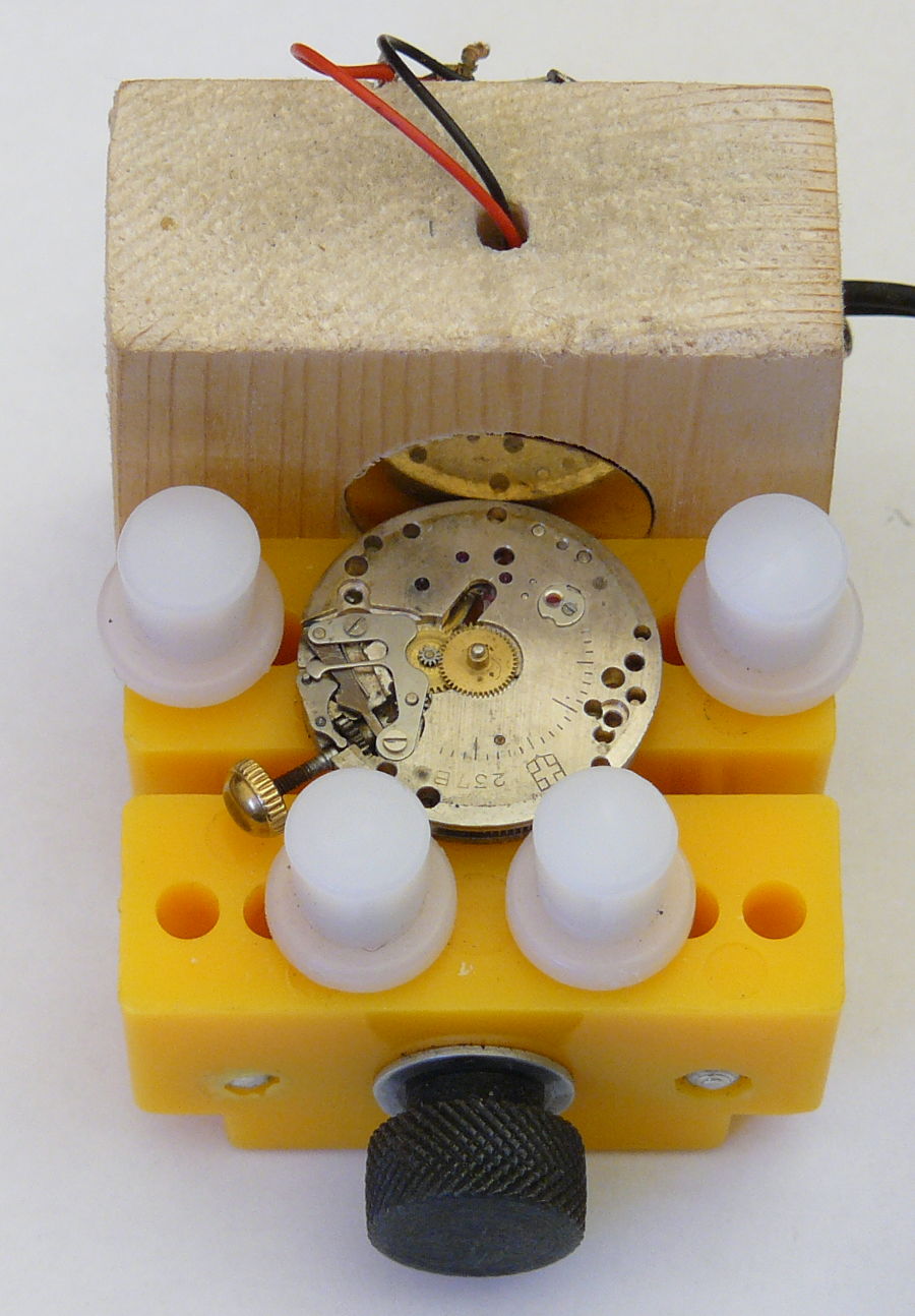
Sensor and vice
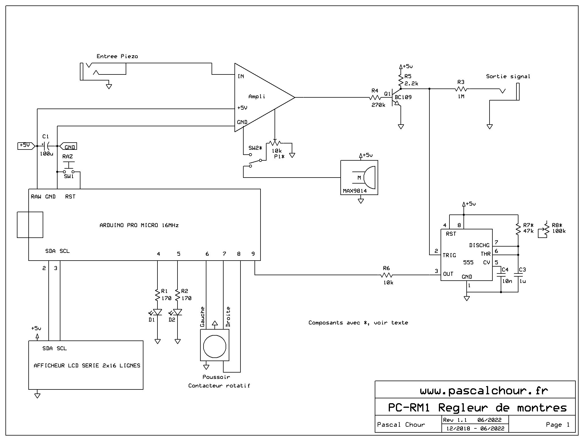
Schéma
The amplifier schematic:
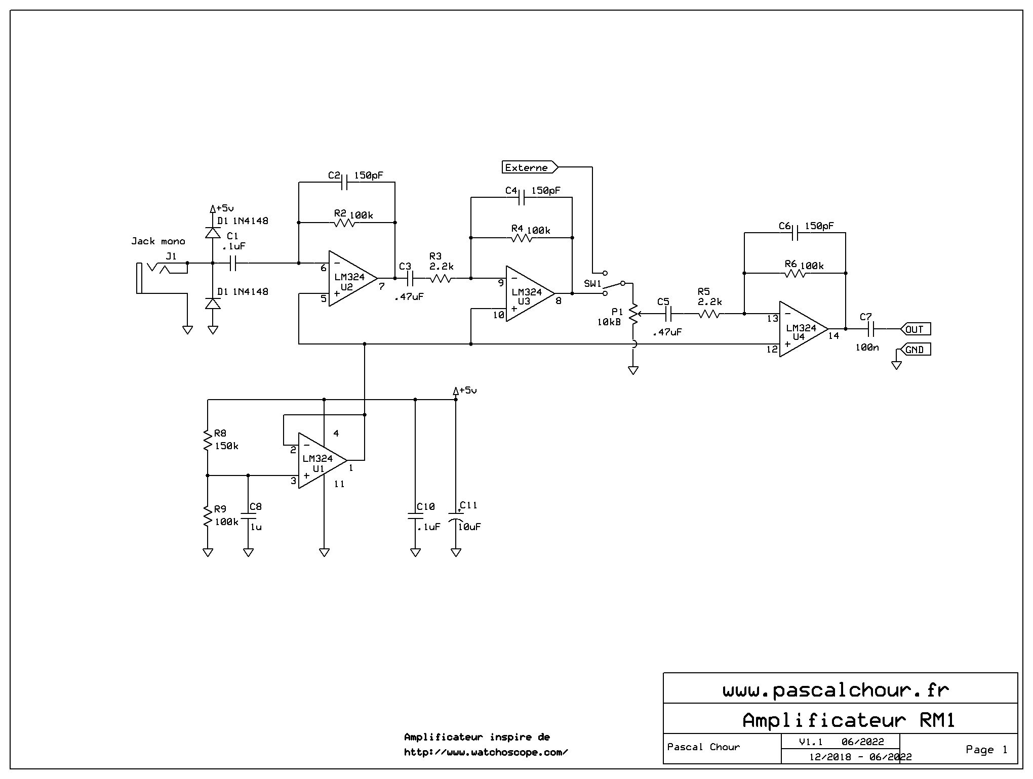
Schéma
Comments on the schematic
P1 is a log potentiometer.
MAX9814 and SW1 are optional. I wanted to have on the device a built-in microphone sensor with its own amplifier (the MAX9814). The results are correct if the watch is noisy enough.
SW1 is used to select either the output of the piezo amplifier or the output of the MAX9814's microphone amplifier.
If you do not use the built-in microphone option, delete the MAX9814 and replace SW1 with a strap.
The multi-turn potentiometer R8 is used to set the duration of the pulse generated by the 555 as a function of the associated capacitor.
The duration of the pulse T = R8 x C3 x 1.1 where R8 is expressed in ohms and C3 in Farads.
Thus, for a duration of 50 milliseconds with C3 = 1μF, R8 is approximately 45kohms.
During this "blanking" time, no signal is taken into account by the microcontroller.
50ms is the duration that I choose. It makes it possible to avoid counting possible parasitic shocks as being "tick" or "tock". It is compatible with periods up to 36000 beats per hour. On the other hand, if you have a watch whose beat count per hour is greater than or equal to 72000, then you will not measure anything.
The choice of this pulse duration belongs to you. If you want a fixed duration of 50ms, you can replace the multi-turn potentiometer with an R7 resistor of about 47kohms.
You can also decide that this duration is too big. You will then reduce the resistance, with the risk that some parasitic shocks that follow the impulse that you want to measure disturb the measurement.
You can also decide that this "blanking" time of the measurement should depend on the number of beats per hour of the watch. In this case, you will be able to modify the program of the device so that this adaptation is automatic and you will regulate the duration of the signal on the 555 at around 5mS.
For my part, I put a potentiometer for the case where I will one day fall on a special watch requiring a modification of this duration. But I did not find it useful to put this potentiometer on the front pannel. It is nevertheless an option that you can consider. That will make a setting of more...
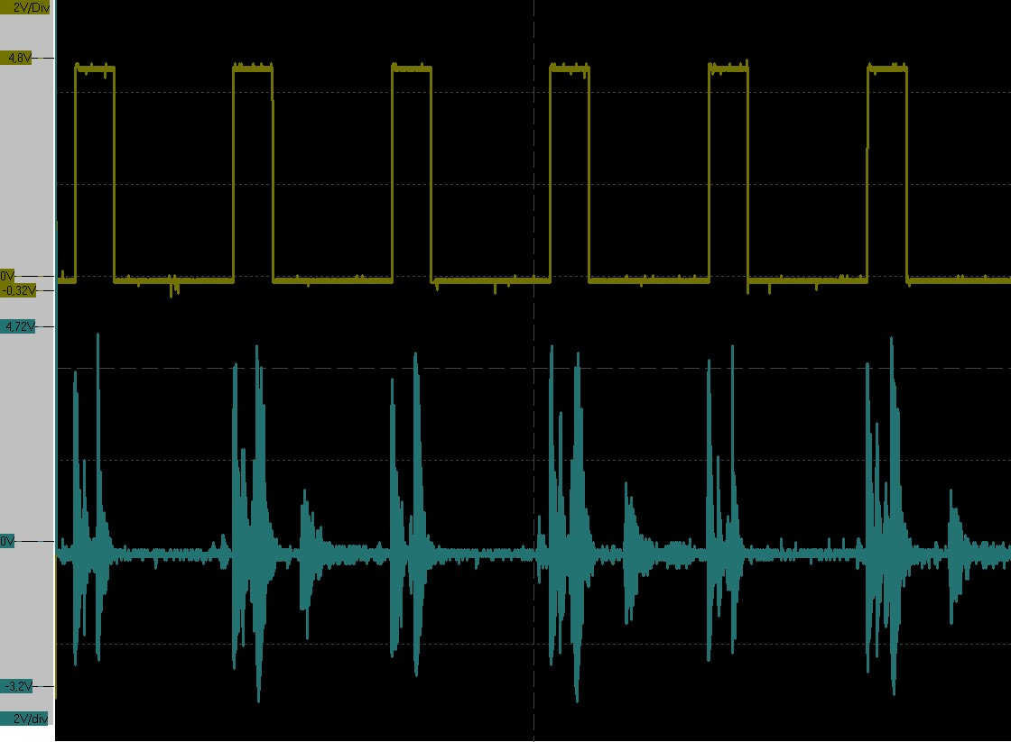
The following trace comes from a capture of the amplified signal (in blue) and the resulting signal after passing through the D flip-flop.
D3 and D4: A piezo sensor can generate a fairly high voltage that could destroy the operational amplifier. D3 and D4 allow the input voltage to be limited to approx. +/- 0.6V.
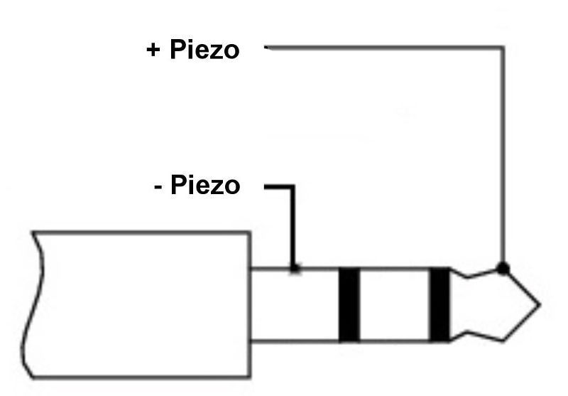
The wiring of the Jack input jack is usual. The body at (-) of the sensor and connected to the ground of the assembly, the (+) on the first ring and the tip (for a stereo jack) or only the tip (for a mono jack).
User Interface
I wanted to make a device very easy to use, with very few commands. This means that a lot of settings available on other devices are not present. Is it a problem ? In practice, no and for the following reasons:
- the settings proposed by the device proposed here are sufficient for most cases.
- If this is not the case, then you still have the option of connecting the device to a computer and then you will have flexibility and ease of use that you would not have with a device dedicated.
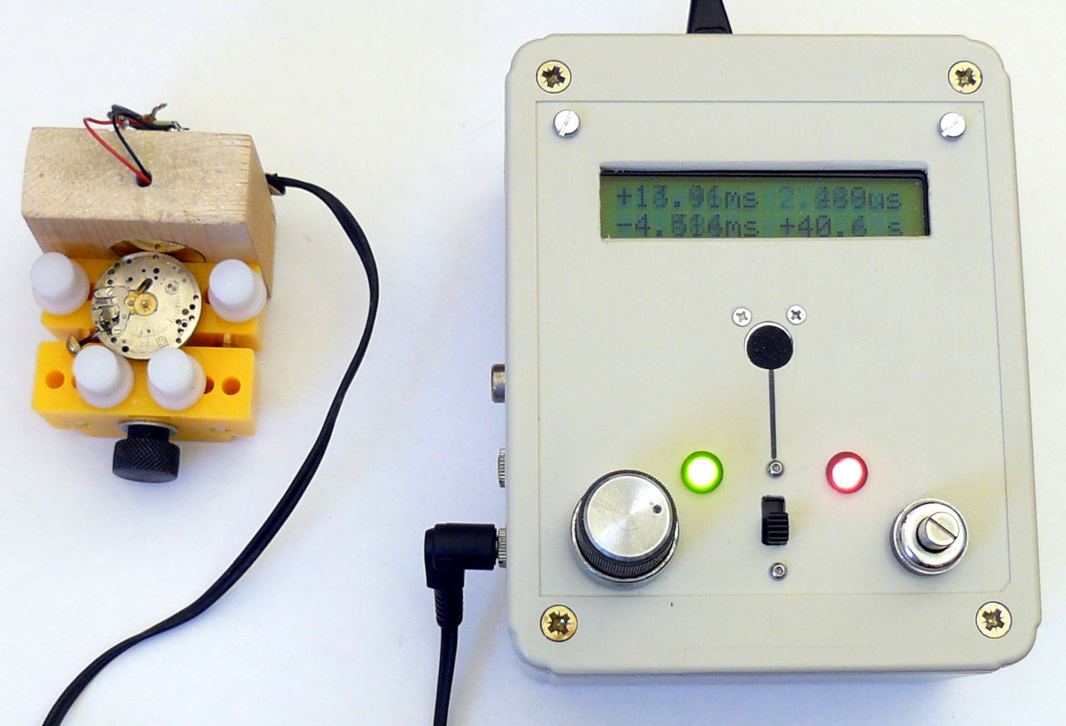
The device therefore includes an LCD display, two LEDs (red / green), a volume potentiometer and a rotary switch.
Optionally, you can add a switch to select the sensor (built-in microphone or piezo). That's what I did but more to experiment than anything else. Practically, you can switch from the built-in microphone sensor.
The instructions for use are as follows:
When the power is turned on, the display will show you the default number of beats per hour. If it does not suit you, turn the switch one way or the other until the number of beats per hour is right for you.

Menu for the beat selection
The available values are programmed. There is no automatic search for the number of beats. It is not that this function is difficult to achieve but in practice, it is not very reliable, especially if your watch is very out of order.
Once the number of beats per hour is selected, press the same switch to trigger the measurement.
Display in measurement mode
More generally, pressing the contactor triggers the measurement if it is not in operation or pauses it (a press) or stops it (two presses) if it is on.
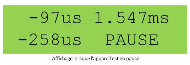
Display in pause mode
The other button is used to adjust the volume. In practice, you should not have to touch it after the first adjustment, unless you change the sensor.
The volume is correctly adjusted when the two LEDs are alternately beating regularly.
If the LEDs do not flash alternately, it means that the volume is not high enough. If one or both LEDs are still lit, the volume is too high.
If the LEDs blink erratically, it is likely that the volume is too much or not high enough, or that your watch has a very big problem that goes beyond a simple adjustment.
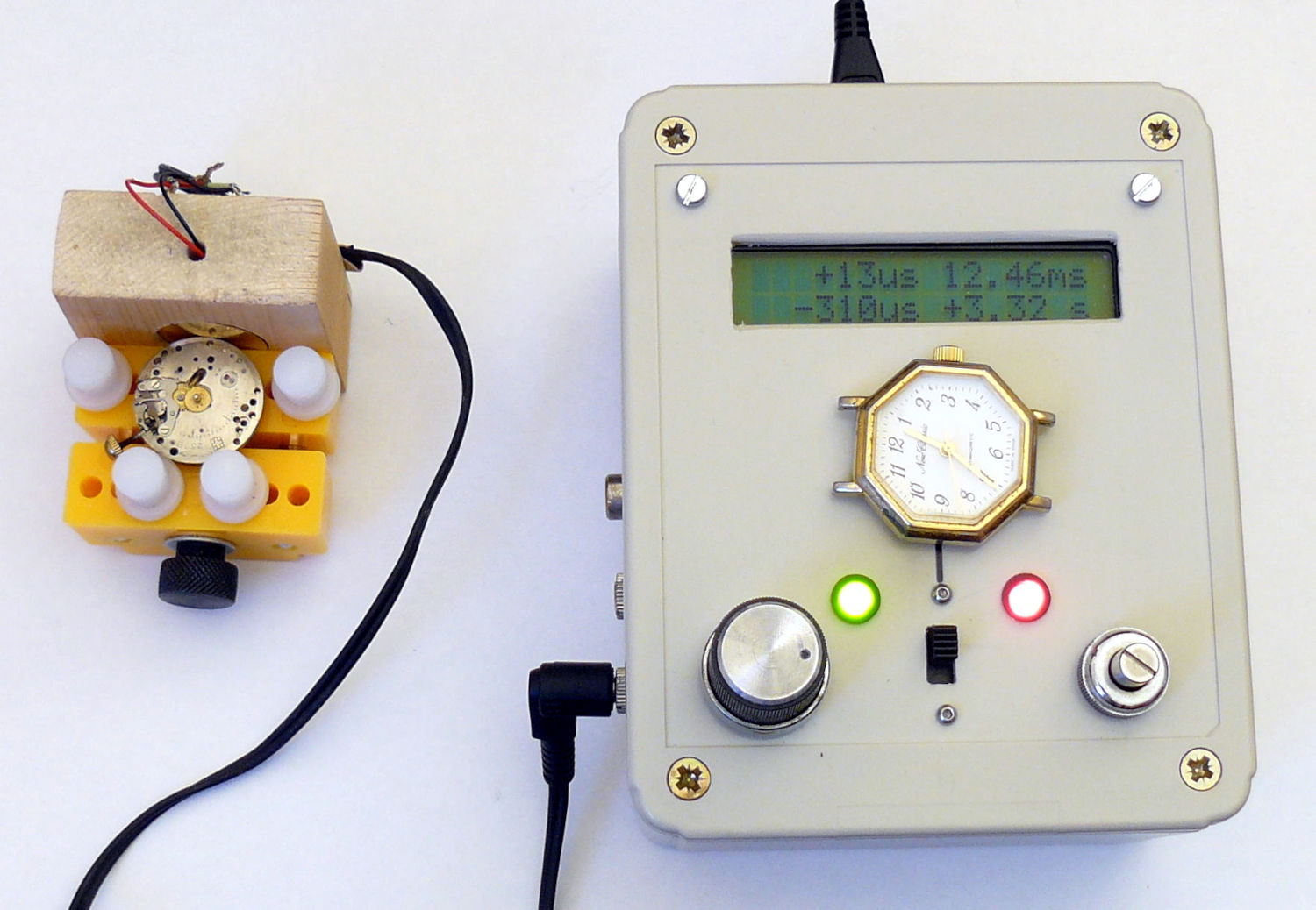
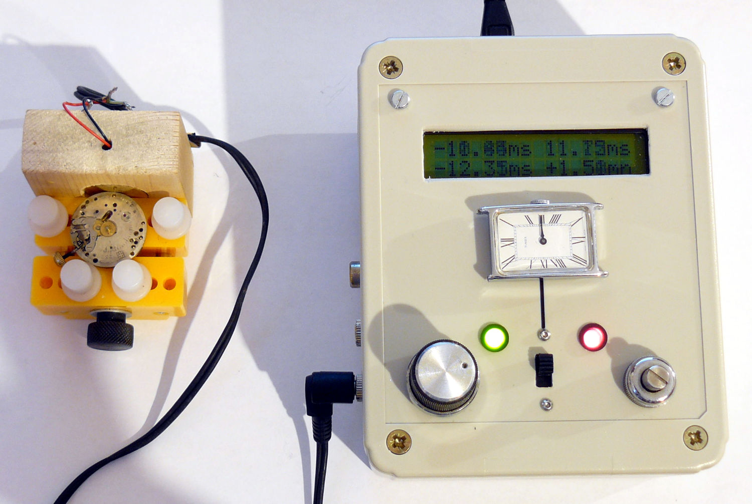
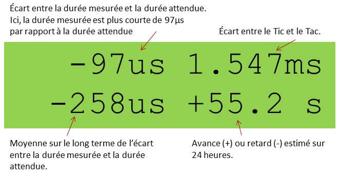
When the measurement is triggered, the display shows:
- Top left: the difference in plus or minus between the measured periods and the expected period. This is an average value over twenty measures. The + sign means that the measured period is greater than the expected value. The minus sign means that the measured period is less than the expected period.
So, if you have a + sign, the watch delays. If you have a sign - the watch is moving forward. - Above right: the difference in absolute value between the "tick" and the "tock". If this difference is high (it is rarely zero), a setting of the stud support is to consider.
- Bottom left, the same as the top right but the long term (calculated average since the beginning of the measure).
- Bottom left: estimated advance or delay by 24 hours. The + sign indicates that the watch is advancing by the indicated value, the sign - that it delays the indicated value).
When there are no significant values to display (no measurements made), the displayed values are represented by hyphens "---".
The display units are automatically selected by the program. They are expressed in μS, ms, s or mn. "***" means an overflow.
Generally, one starts by adjusting the difference of the periods until it is as close as possible to zero. This adjustment should be done for several positions of the watch (horizontal, vertical ...).
When the result seems satisfactory, we re-trigger a measurement campaign focused on the advance or the delay per hour.
Accuracy and resolution of the device
The microcontroller clock determines the accuracy of the device. This clock has a frequency of 16MHz. It is usually accurate to less than 1%.
The program measures time with a resolution of 4μs. The accuracy of this resolution depends directly on that of the clock.
Take the case of a watch whose beat is 18000 rounds per hour. The duration of a beat is therefore 400ms and the duration between a "tick" and a "tock" is 200ms.
A resolution of 4μs means that practically, on a set watch, we will have 400ms +/- 0.004ms, ie a real value in the interval [399.996,400.004] ms at +/- 1%.
This value is quite correct for the measurement of the beat period. On the other hand, it is hardly bearable for the measurement of the advance / delay per day. Assuming that the error due to the resolution is cumulative, we will have an error per hour of about 0.072 seconds that is +/- 1.728 seconds per day at +/- 1%.
Nevertheless, human being what it is, one wishes to have an indication of the advance / delay per day as soon as possible, even after 10s of measurement.
The device therefore displays as soon as it can (approximately after twenty measurements) an approximation of this advance / delay.
December 2018
The image below represents the prototype I used for software development. Compared to the final version, we note the presence of a DC-DC voltage booster to produce 9V from 5V. In this version, I was using the TL074 from the original Watch-O-Scope setup.
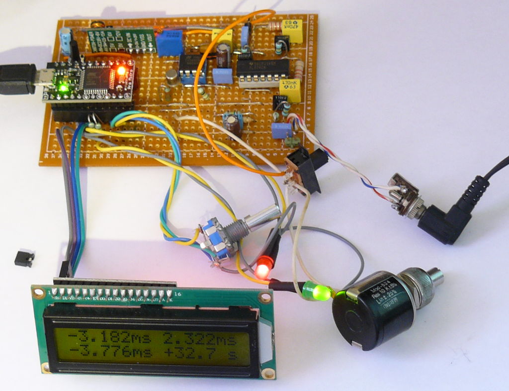
Prototype
Here are two examples of using the built-in microphone. One for a Chinese watch that beats at 21600 shots per hour, the other a Timex that beats at 18,000 shots per hour. Note that in this version, the program displayed the advance delay per hour and not per day.