Introduction
 The goal of this page is not to provide a
universal and complete method to repair our dear old
antique electronic equipment. Firstly, it is only
about radio sets with vacuum tubes. There
are already books on this subject which will be able
to satisfy the universal need. For instance, if you
are looking for repairing methods of radio sets, you
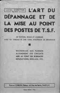
can try to obtain the book called
"The art of repair
and fine tuning of T.S.F [radio sets]." (1945, in french)
from Lucien Chrétien, E.S.E. engineer (today the
university is called SUPELEC), available in all good
bric-à-brac trade stores or the training from Eurelec
The goal of this page is not to provide a
universal and complete method to repair our dear old
antique electronic equipment. Firstly, it is only
about radio sets with vacuum tubes. There
are already books on this subject which will be able
to satisfy the universal need. For instance, if you
are looking for repairing methods of radio sets, you
can try to obtain the book called
"The art of repair
and fine tuning of T.S.F [radio sets]." (1945, in french)
from Lucien Chrétien, E.S.E. engineer (today the
university is called SUPELEC), available in all good
bric-à-brac trade stores or the training from Eurelec  on
the same subject (around 1960, in French).
on
the same subject (around 1960, in French).
And if you know nothing about the radio, you'll find in "TSF without mathematics" from Lucien Chrétien, a good introduction on that matter (1935, in French).
Nevertheless, it is sometimes good to consult several sources. Certain methods can be more adapted than others according to the frame of mind at the time or the mood of the repairer. Here is my own manner of going about things. I remind that it is the method of a repairer and not a collector. My objective is not necessarily to keep the radio set such as it was during its building but to restart it.
Basic Tools
|
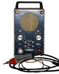
I will not talk about about standard tools (spanners, screwdrivers, hammer (no!, no need for a hammer), etc). A powerfull soldering iron is highly recommended. As for me, since more than 35 years, I use a 100W Engel Lotter soldering iron. On measuring equipment, in addition to the electronic multimetre, one of the most useful ones for me has been the Signal Tracer. The one that I use (Heathkit IT12) has valves. It also has a test function of on circuit passive components is very efficient (noise locator): you put a clip to one extremity of the component that you have to test and the test probe to the other. If you hear strange noises (frying or crakling noises) from the signal tracer speaker, the component is to be considered suspicious and replaced. |
|
|
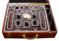
If you have the possibility to get a tube meter (lampemetre), don't hesitate. It will allow you to sort your tubes and to avoid spending time to try to repair a radio set with an out of service tube. A capacitor meter can be useful, for instance, to find the value of a capacitor which has no indication or an erased indication. As for me, I managed without one for 30 years but in 2000, I decided to buy one. |
|
|
The oscilloscope allows you to gain time with certain measurements or research of signals but it is not necessary except if you have a radio, which is completely misaligned or if you have to proceed to align one. Then, you will also probably need an HF generator. One essential thing is a book about radio tubes, their characteristics, their sockets, which will allow you to take the measurements in the right places and to interpret them correctly. A very good book about radio-tubes is the multilingual International Radio Tubes Encyclopaedia. |
|
As we can see, the basic equipment can be light and allow to handle most of the situations. It is rather necessary to link to it a good reserve of components, which are adapted to the context (capacitors sometimes supporting high level voltage, 1/2 watt resistors or more... and sometimes (often), replacement tubes). If you have any problems about the components, you can consult this page.
First observations
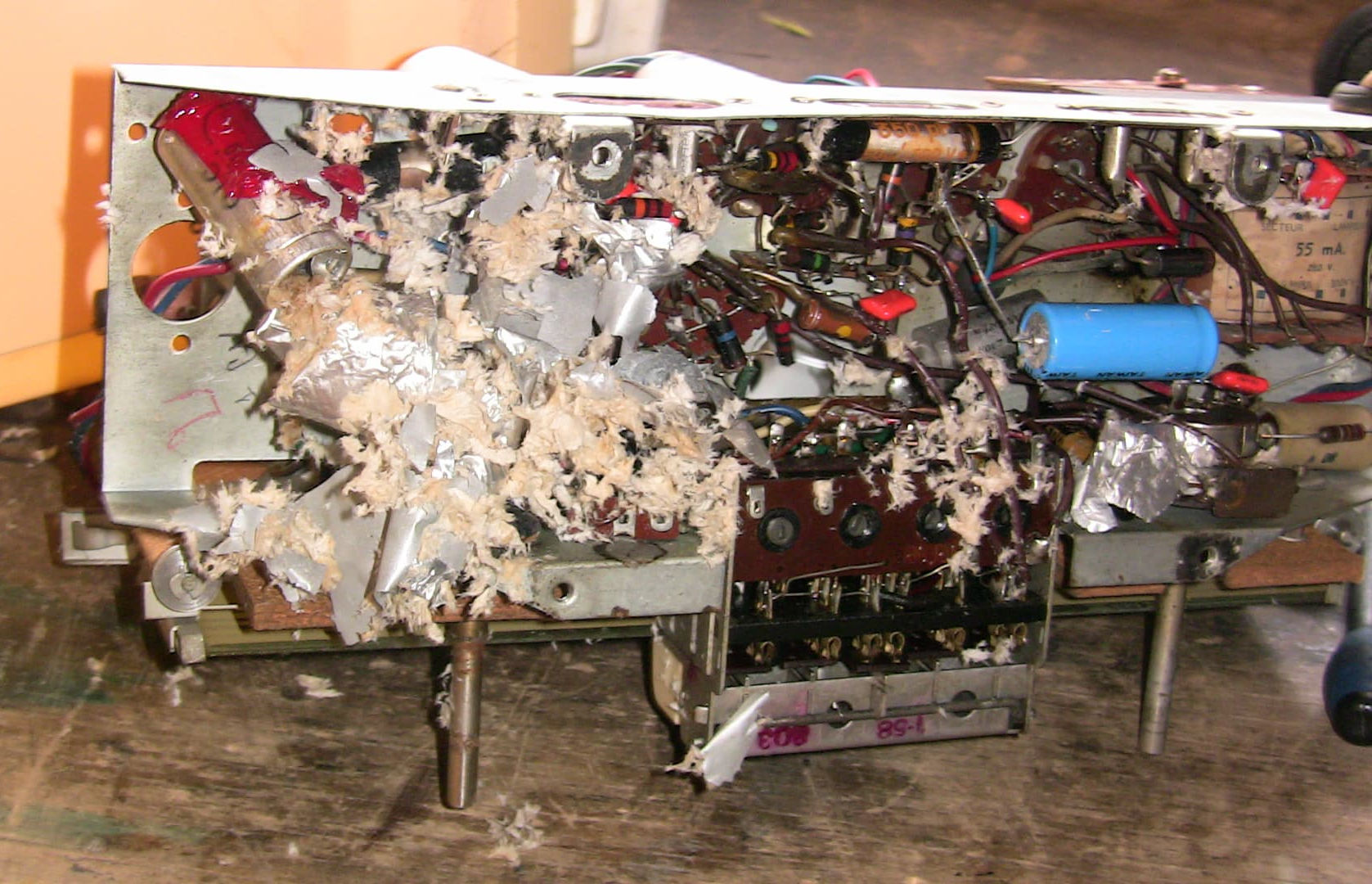
Perhaps you bought a radio set from an antique dealer or one of your friend brings you their granddad's radio set, which had been stored in a cellar or a loft for 30 years.
The first observation of the external general state gives you an idea about the work you will have to do on the cabinet. Ask youself if it is worth it... Generally, radio sets are disassembled by the rear. Disassemble the rear panel. There is sometimes a trap door located under the radio. Also disassemble that and examine it inside.
Often, the first observation is that there is a lot of dust. Before cleaning, have a look on the side inside the radio and on the reverse side of the rear panel in order to see if there is a radio-tube diagram. If it is there, copy it on a paper with all the references. Why? Sometimes, diagrams are on a paper glued within the cabinet. The paper is old and with the heat, at times, it risks falling in to small pieces. Sometimes,the diagram is printed on the rear panel. The printing can be almost erased and if you try to clean the panel, there is a risk you completely erase it. A compromise is sometimes found somewhere in between a light dusting or to see nothing. Use a soft brush to proceed.
Examine the state of the visible electric wires. Wires with only isolating rubber age often age faster than those isolated with material. All cables with insulation in a poor state must be changed. If you have to change the cable of the main supply, you can consider replacing it with an electric wire with earth plug, the earth being connected to the chassis ground. Beware of disappointments: it often happens that a radio set has electric leakage and trips your electrical installation. It can be difficult to find where the leakage comes from. In that case, don't connect the earth and verify that no metallic part of the radio set is approachable in normal functioning (verify particularly that buttons do not have approachable metallic parts connected with the chassis).
If the electronics seem in a good state (cable with good insulating, all the tubes in their sockets, no sign of leakage from smoothing condenser, no cut fuse...) you can try to turn on the radioset. In all other cases, it is better to refrain until the obvious problems have been repaired.
First power on
Verify the functioning voltage of the radio set. Some radio sets work only in 110v. It will be necessary to use an auto-transformer if you are in Europe. For the others, put the voltage selector in the good position (230-240V in France). It is possible that the on/off switch (often on the volume button, sometimes the waves band selector, sometimes the tone control) is out of order. For that reason, it's better to connect the radio set to a plug with an on/off switch.
During this phase, you must have the possibility to observe the insides of the radio set. Turn the volume up to at quarter and select a powerful station. Don't forget to plug an external antenna if your radio set has no internal antenna (it is generally the case with old radios). Turn on the radio. Observe the tubes attentively and more particularly the valve rectifier (generally placed near the transformer, when there is one).
If a tube gets quickly bright red, immediately turn off the radio. The same if you hear crackling in the electronic components (not from the speaker) or if smoke appears.
If your radio works, so much the better for you. But we have not finished the job yet. Probably, you'll have to clean the radio as described below. If it does not work or if you are in an intermediate situation (bad sound, snoring...), you will have the happiness to spend one or more fascinating weekends with it.
Chassis dismantling
Generally, you have to remove the buttons. These are sometimes simply pushed on to the axis, or more often, screwed. Screws are often rusty and it is difficult to unscrew them. A little penetrating oil should allow you to to overcome it.
The chassis is often fixed to the cabinet by screws or bolts which are accessible from the inside, or from the bottom. The speaker is often directly fixed to the cabinet by screws. The length of cables connecting it with the electronics is sometime insufficient to allow to take out the cabinet without disturbing the speaker. In that case, two solutions: Either you disturb it, or you cut the cables which connect it with the electronics. The first solution is often the best, particularly, if you have to restore the cabinet: in that case, you will anyway be obliged to disturb the loudspeaker.
Take out the chassis of the cabinet with the loudspeaker if you disturbed it and put the whole on a work plan.
Careful! Never switch on a radio without the speaker. You have the risk of destroying the output transformer.
Tubes dismantling
If you have not got the layout diagram of the tubes, take a sheet of paper and a pencil and make a layout of them in regards to the chassis. Remove tubes one by one by writing their reference on to the diagram. When you remove the tubes, take care of not putting your fingers in the place where their references are printed. This print resists often badly to the effects of time (especially with the 1950s tubes). If the references are erased, observe the tubes under a certain angle in the mist of your breath. If you are lucky, perhaps you will see a small shiny difference and you will able to retrieve the reference, wholly or partly.
Clean the tubes by taking care of not erasing the references. As for me, I systematically rewrite the reference on the tube with an permanent felt-tip.
Dial dismantling
It's better to disturb the dial to clean it. It is often a printed glass plate. Carefull! The glass plate and the printing are fragile. To disturb this plate, it is sometimes necessary to remove the supports of the lighting lamps. The plate is often maintained between metallic clips squeezed by one saw. Unscrew the saw by maintaining the glass plate so that it does not fall. Generally, the metallic clips squeeze the glass plate via rubber to absorb the dilations and avoid a direct contact glass-metal. These rubbers are generally completely burned and must be replaced. For my part, I use insulating joints for windows in adhesive band.
If you have a scanner, I advise you to scan the dial. If a misfortune should one day happen to it, you can always redo one from its digitized image.
Cleaning the chassis and the electronic parts
Dust the chassis and anything accessible to you with a brush. If you are determined you can clean it more profoundly with White Spirit. Be careful not to shock the small strips of the variable condenser during this operation.
Turn the chassis and clean the inside.
Clean all the accessible contacts (range wave selector of wave, variable condenser, in particular at the level of axis) with an anti-scratch spray. Do the same with potentiometers, tube sockets, antenna grips, H.P and pick-up plugs, etc. Grease the mechanical axis of the variable condenser and the possible pulleys of training of the needle of stations.
To finish, write the tubes references on the chassis near the sockets with an permanent felt-tip.
After this treatment, your radio will be as good as new and that might increase your motivation to repair it.
Repairing the electronic
For old radios, a common cas of failure is the smoothing capacitor which is out of order. If it seems old (big with regard to the announced capacity ) or if you see trace matter underneath, changes it. This will spare you many concerns later. If it is fell out of order during the long period of inaction of the radio, you have a chance that the valve is still good. Otherwise, it will probably need be to change.
Observe the passive components. Check whether there are burned or darkened resistors or if there are any unsoldered components, etc. Change the electrolytic capacitors with trace of dielectric fluid or those whose glass envelope is broken. If you have a doubt about the value of the condition of the capacitors situated near the power supply (generally, 0,1µF), change also. Here are some remarks on the marking of the capacitors:
- Some capacitors have their values in mF. You must read µF. So, 0.1mF = 0.1µF.
- Some capacitors have their values in mmF or µµF. 1mmF = 1µµF = 1pF.
- some capacitors have their values in cm (centimeter). 1cm = 1,113pF. Generally, we can refrain from doing the conversion when we have to replace it and we can consider that 1cm=1pF except for the capacitors which are used in oscillators. In that case, the replacement value has to be clother (the same) as the original value.
Redo the parts of the cabling which seem to you in poor condition.
If you have a lampemetre, verify tubes and change those who are bad.
If you have a measurement equipment wich allow to check the components (Cf. Signal Tracer), verify the decoupling capacitors and the resistors. Change all the doubtful components.
Put tubes on to their sockets, verify and change the fuse if necessary and switch on the radio. If you are lucky, the problems of supply should have now be solved.
If other lamps than the rectifier redden, you will have to look for a defective component (cut capacitor either in short circuit or cut resistor). Methods to the repair such as that mentionned at the beginning of this page should allow you to succeed.
If the radioset remains mute (or if the sound is execrable), the Signal Tracer should allow you to find the breakdown. One needs a minimum of intuition, to have an idea of the various stages which constitute a radioset and have a book supplying the connection diagrams and the characteristics of tubes.
Signal-Tracer
A very usefull tool for repairing radio sets is the Signal Tracer. Have a look to the IT12 user manual (pages 19 - 21) for more informations in english.
Some classic breakdowns
Many breakdown are due to cut capacitors or capacitors in short-circuit. The most concerning are the electrolytic capacitors and the paper capacitors which have tar. For the latter, do not be alarmed by the indicated voltage (1500v for example). They generally can be replaced by capacitors (paper, polyester, MKS...) with service voltage beetwen 400 or 600v and which we can still find easely. If you were not able to measure the continuous voltage of the capacitors in circuit before the replacement, do it after to ensure that the new capacitor is correctly sized. Attention: a cut capacitor acts as a reminder to check a possible cut resistor, especially when it is in parallel of the capacitor.
exploded electrolytic capacitors
It is not rare that you have to change most of the decoupling or link capacitors. On the other hand, change mica capacitors only in you have no other choice. These are very stable over time and except mechanical problem (often, the eyelets), they do not generally cause concerns.
some old resistors were made by winding a metal wire around a core. The end of the wire were soldered to two caps. In time, bad contacts form. The breakdowns which result from it are not always frank. It is sometimes necessary to shake the component to verify if it does not introduce dysfunction.
The carbon composition resistors are not the best of things in electronics. If they are solid, they derive enormously over time. Luckily, their value tends to increase. Why luckily? Because you'll be able to test them on circuit without unsoldering them. If the value you read on the ohmmeter is higher as their marking (> 20 %), you must change them. A too high value (with regard to their marking) can entail a bad polarization of tubes and a non-optimal functioning of the radioset. On the other hand, a lower value as their marking does not bring very reliable information without knowing the radio set diagram. In that case, you must unsolder one extremity of the resistor and redo the measurement. These resistors were common in the 1950-1960s radio sets.
Cleaning the dial
You can clean the front of the glass dial can be made with any cleaning product for glass. The printing is normally on the rear face of the glass dial. You have to take some precautions. If the printing is covered with varnish, you can proceed with the front of the glass dial without risk. If the printing is not protected, attempt to clean with a soft brush. Unfortunately, this simple cleaning can sometimes remove a part of the printing. Very often, it is possible to see if the printing is still protected. If some letters or numbers are already gone, or if you see some printing particles on the glass dial, then, the printing is in a bad state. So, proceed very carefully not to aggravate too much the state.
Cleaning/repairing the cabinet
If the case is made out of bakelite or vinyl, a cleaning with "Marseille" soap (household soap) should be enough. You can finish this cleaning by a product intended for renewing plastics.
If the case is made with a wood veneer, there are several possibilities. The cabinet were generally varnished and had a very shiny look. If this varnish is in poor condition (cracked, tired), you can attempt a complete restoration. Remove the varnish with a paint burner or by chemical varnish remover. When the varnish is removed, sand the veneer. If it has a beautiful look, and if you are not familiar with varnish, you can put linseed oil on it. Its final look will be matt but the wood will be well protected well and the result will be a success. However, this approach will be not approved by those whose want a restoration to original conditionbecause the cabinet will not be completely the same anyore.
You can also try to varnish it with a brilliant varnish but you will not able to obtain the shiny aspect of the origin.
The ideal is to do a French polish but the technique is difficult and requires a certain experience. An other approach consists in using a product for vitrification applied with a fine paint roller. The veneer must be then perfectly cleared of any track of varnish. The result will be close to the original and the cabinet will be very resistant against small accidents.
Many thanks to Mme Dominique Jaurola for having checked the translation.