CHOUR - Very low power Geiger Muller counter PC-GM5
Device : Geiger counter
Date : 2013-2016
Type : PC-GM5
Brand : Chour
Main parts: GM Tube SBM20, MSP430 Texas Instrument family processor, Imex module for High Voltage
Main characteristic : Average power consumption around 30µA.
Software : Downloading.
Version française : 
Introduction
Apart from the Gamma-Scout, most of the mass-market Geiger-Muller counter available (in 2013), have a limited range, at least for those who use a microprocessor to manage the data processing. The reasons are multiple:
- The high voltage generator is often poorly designed. Still, there are diagrams on the net offering generators announcing consumption of a few uA. Some modules already built announce a power consumption between 0.5 and 25µA.
- The microprocessor used is not efficient from the power management point of view. But again, some processors (Texas-Instrument for example) are very efficient in this area.
- How is the microprocessor used is not optimal. A common mistake is to delegate the counting task to a software running on the microprocessor. This forces it either to be in continuous operation, or be in sleep and be awakened every time there is a pulse.
The most obvious solution to avoid this problem is to use a CPU counter (which is the case in PC-CGM5 or 6) and raise this counter periodically (every second, every 10 seconds ...)
But sometimes, this option does not take advantage of the most efficient low power modes. PC-GM3 and PC-GM4 propose an other solution with a Real Time Clock PCF8583. PC-GM3 and PC-GM4 using this solution consume less power than PC-GM5 using the counter of the processor.
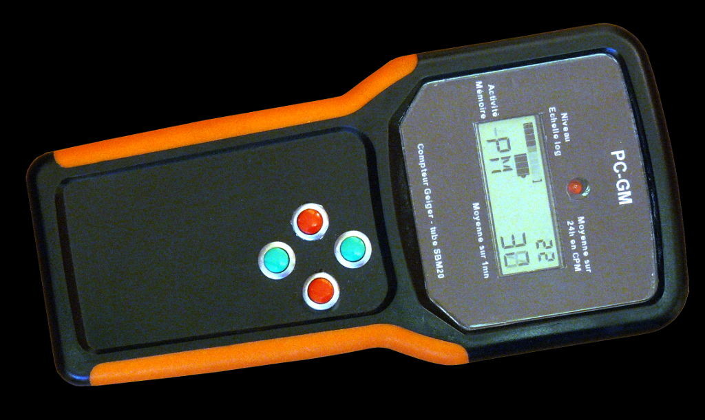
Overview of PC-GM5
As with the previous counters, I've used the following:
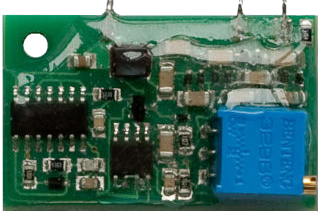
- A high voltage generator IMEX-38-56-1 (in French) with a rated consumption given for 0.5 to 10 uA at 3.3V for generate 400V.
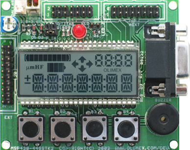
- A MSP430F449 Texas-Instrument microprocessor (Olimex development board MSP430F449-STK2) purchased around twenty euros and manages a display suitable for this type of application
- A Russian Geiger-Muller tube SBM20.
This GMC stores the number of pulses within a certain time interval. Every second, the processor which is normally in standby (mode 3), wakes up, did some checking (keyboard management, USB ...) and return to standby. Every 10 seconds, the processor reads the counter, made his statistical processing, checks alarm conditions and if there is no alarm, return to standby. In case of alarm, the frequency of measurement is one second.
This counter also includes:
- A battery charging module.
- A USB-Serial TTL communication module
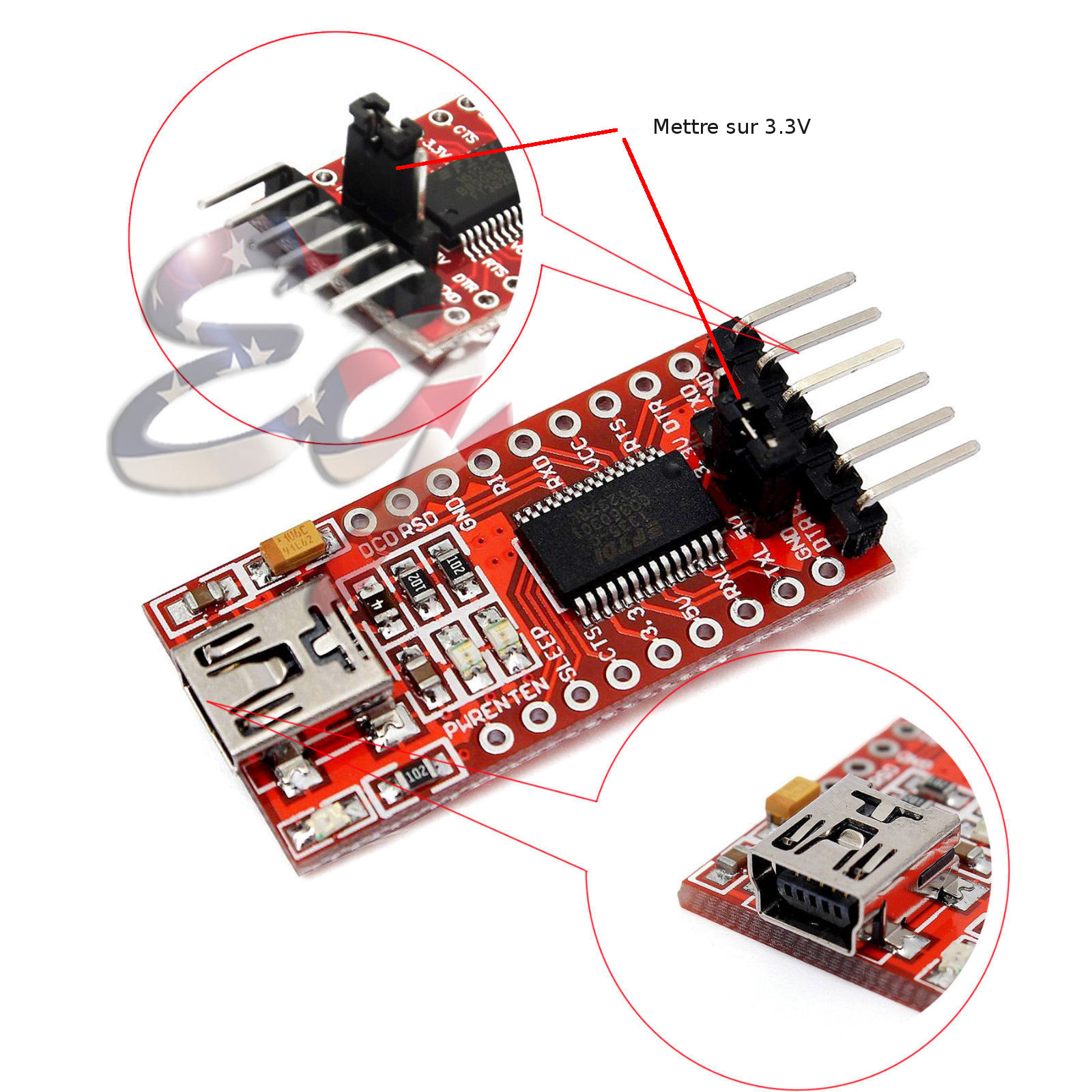
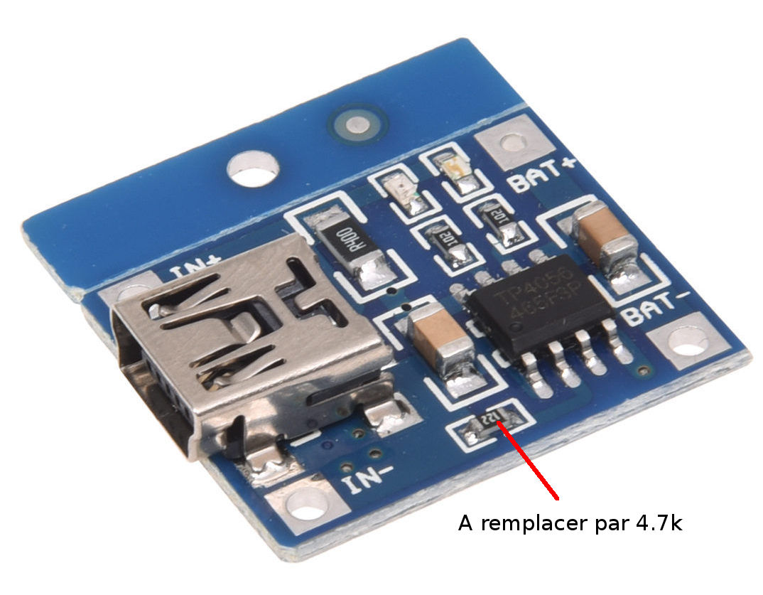
FTDI232 and LIPO Charger (click to enlarge)
The functionnal specification (in French) are available here (same as PC-GM3).
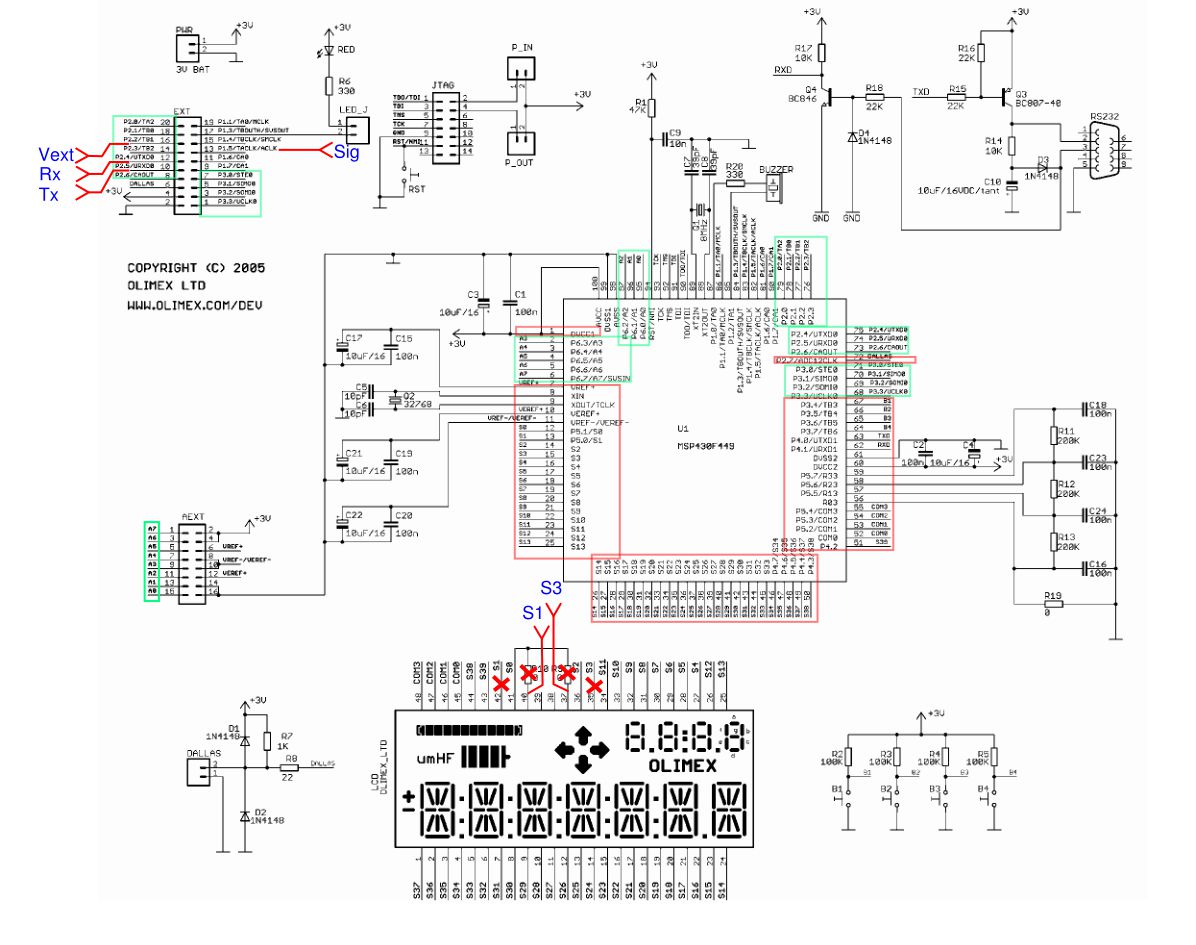
Schematic
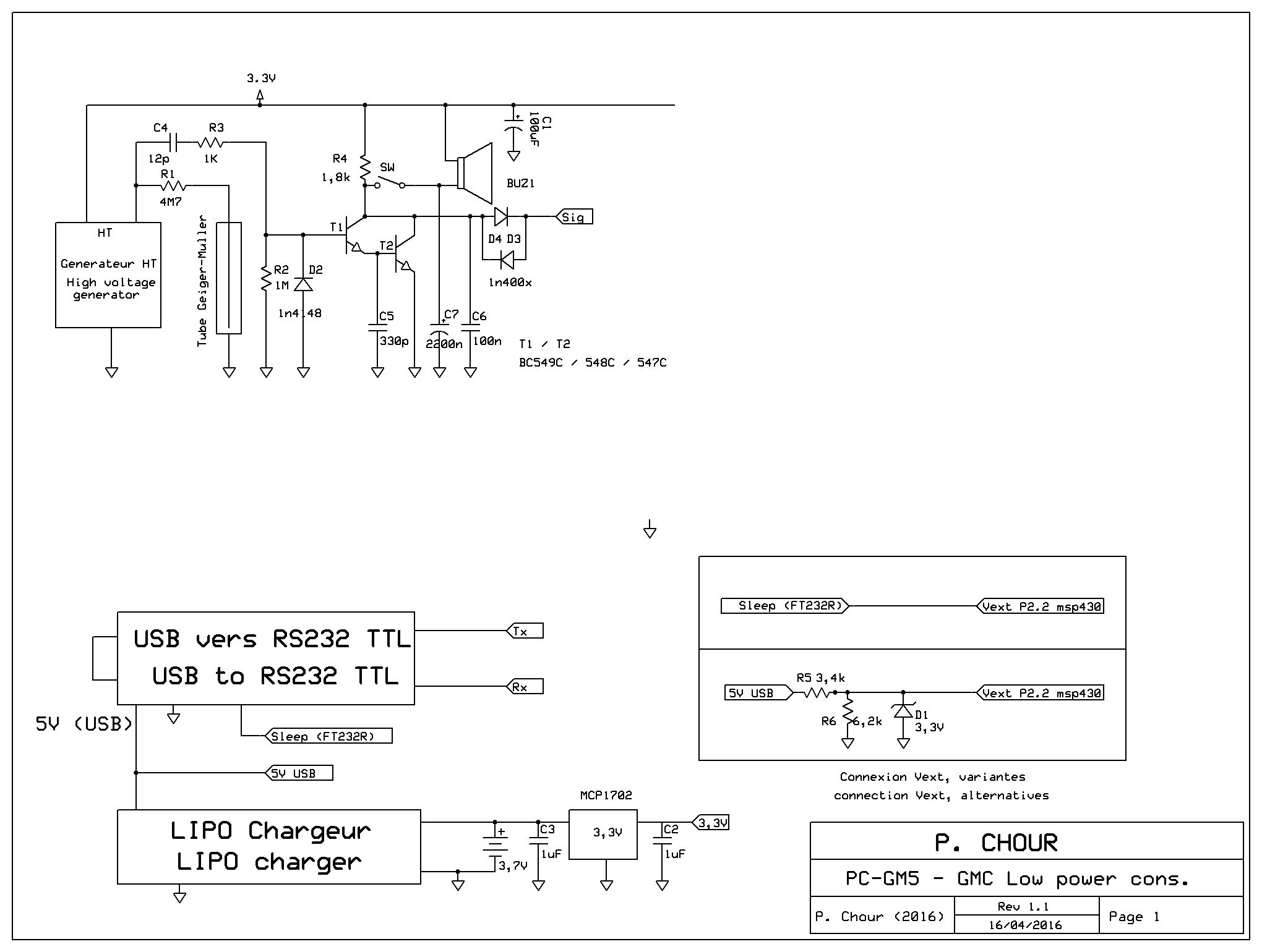
Version with 3V buzzer 1kHz. Click to enlarge
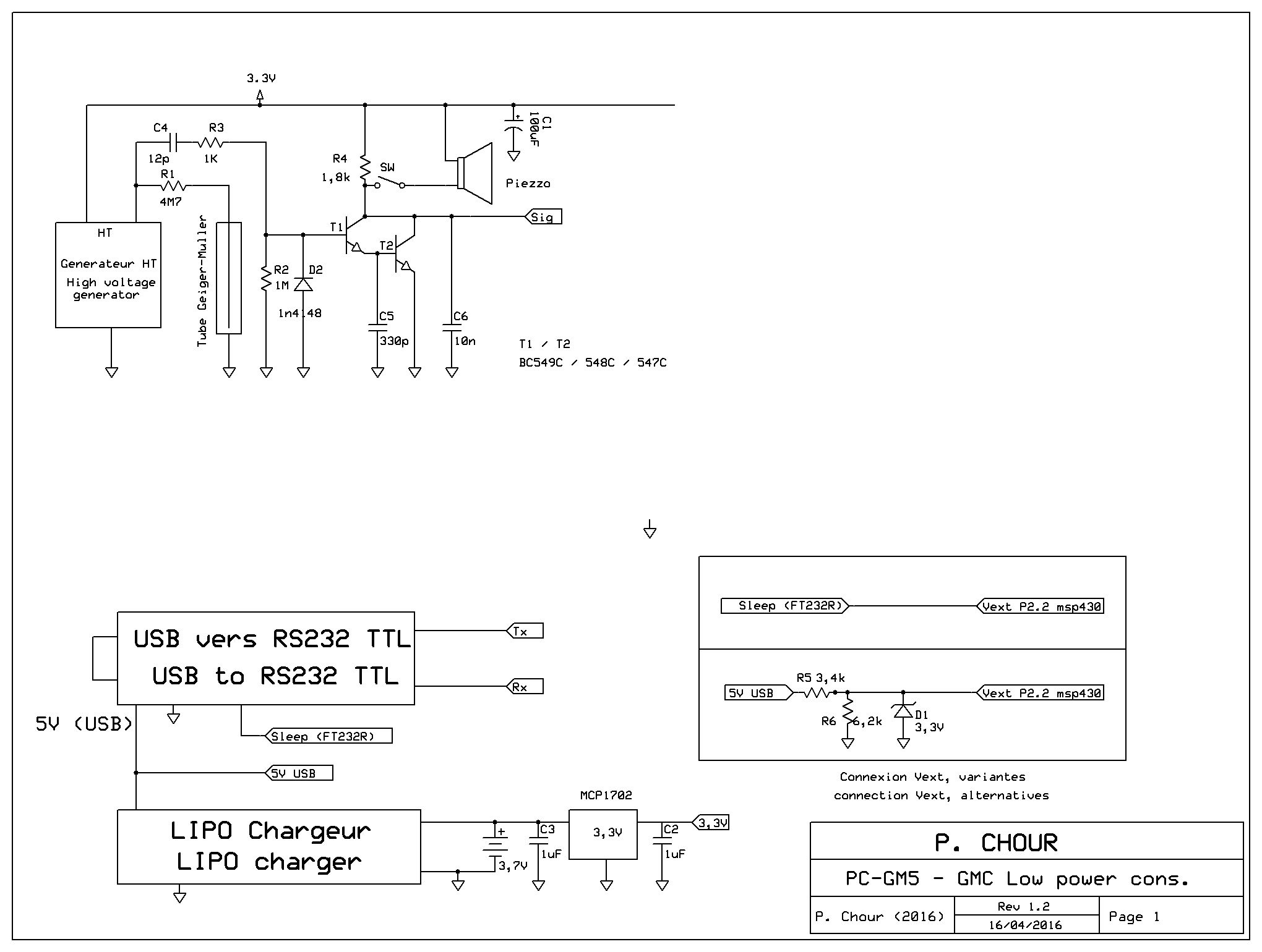
Version with piezzo buzzer. Click to enlarge
The output of the high voltage generator is connected closer to the Geiger-Muller tube. The ground of the tube is directly connected to ground. Detection of the signal is done by the anode. When the tube detects a particle, a voltage spike appears across C4. This peak is amplified by the Darlington formed by T1 and T2 (in my case, I used BC548C because this is what I had in stock but the BC547 and 549 must also be suitable).
On the T1 / T2 collector, the positive potential via R4 falls to 0V and then returns to the positive potential when the pulse disappeared.
The Sleep pin of the T232R is connected to the GPIO P2.2 of the processor. It shows whether an external power supply is connected or not.
TX and RX of the USB module are connected to UTXD0 and URXD0 (P2.5 and P2.4) of the processor and are used for communication between the GMC and a PC. Do not forget to configure the USB module for TX and RX operate on 3.3V and not 5V.
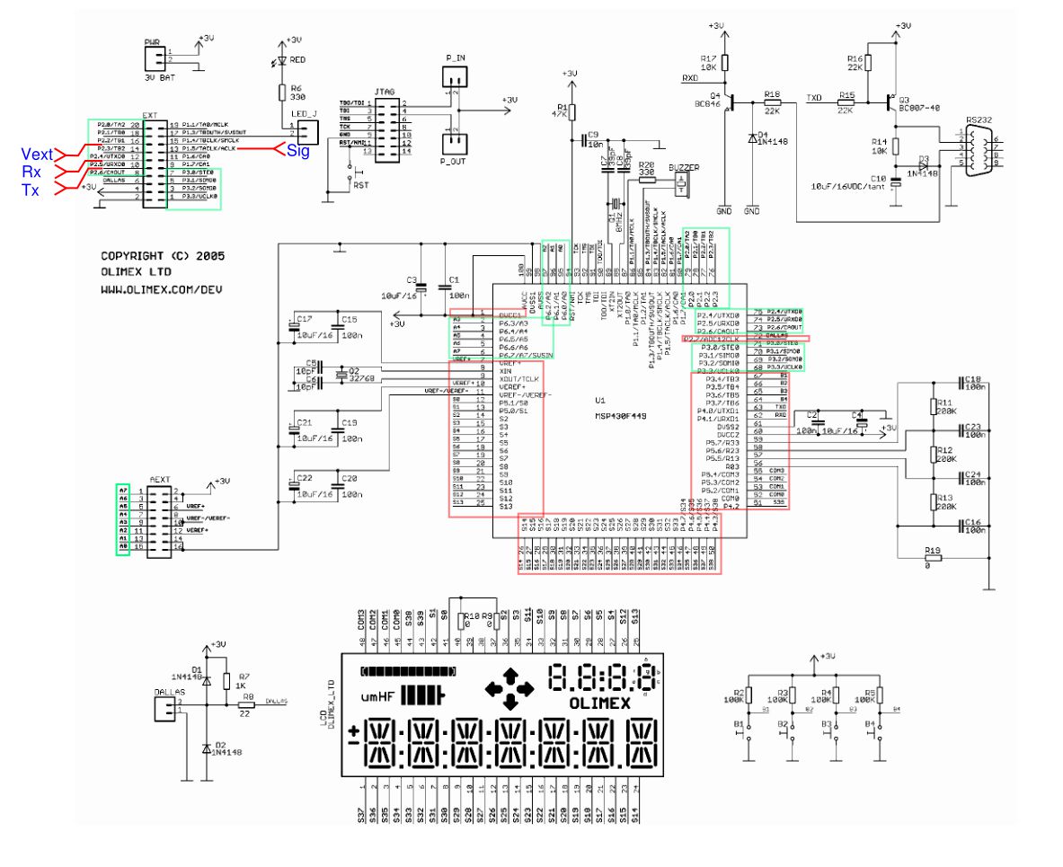
MSP430f449 STK2 without Bargraph modification. Click to enlarge
I consider that the Olimex module MSP430f449STK2 has a bug. Indeed, you cannot use the bargraph as a bargraph. You can fix this bug with these modifications (see the schematic below).
- Remove the resistors R9 and R10 (0 ohms).
- Cut the pin 42 and 35 of the LCD display.
- On the PCB, connect 42 with 40 and 35 with 37.
By doing this, you remove the symbol display "µmHF" and arrows that are not really helpful for the GM counter. Doing that, you have a bargraph to visualize the counting rate in the manner of an analog galvanometer.
The GMC program has two versions. One in which the bargraph is used as a simple warning indicator (unmodified PCB) and in which the arrows flash to the rhythm of the CPU alarm, the other in which the bar graph is used as count rate indicator. The arrows are no longer used..
The indications of these modifications are presented below.
MSP430f449 STK2 with Bargraph modification. Click to enlarge
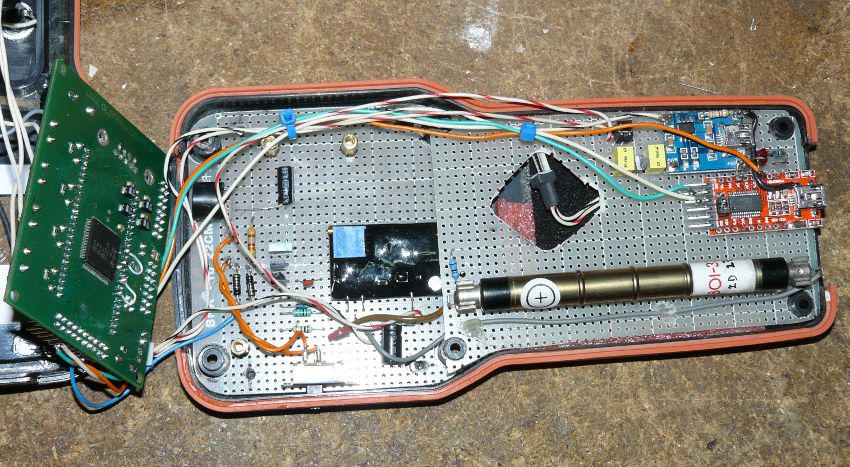
Inside the CGM, analog part.
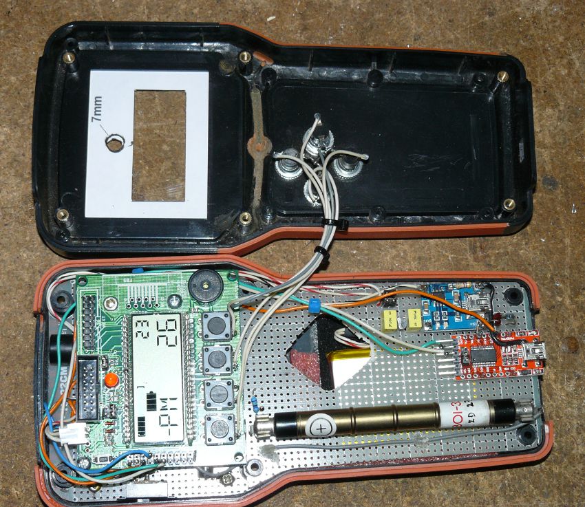
Inside the counter.
Software
The program is developed using IAR workbench. It is necessary to have a JTAG probe to load the program in the Olimex development board. You can download the software from the download page download page.
2013-2016